

I will describe how to make a solar LED garden light from scratch, using the 5252f part which runs the light at night once the light on the solar LED gets low. It also keeps the battery from draining down too much and damaging the battery. It does not have an overcharge circuit. Be careful not to put too much of a solar panel, in milliamps, as you can overcharge the battery. But you might consider larger solar panels for AA batteries (rather than a AAA battery), or in places where the device might be indoors and not get a lot of sun, or only in direct sun for a limited time per day.
Check out my YouTube video covering this article. While this article goes into more detail in some spots, it does not contain all the information in the video, so check out both.
It’s up to you how to mount the electronics. Will it be to replace an existing solar LED device, where the electronics were damaged, or you can’t get to work? You can replace the circuit board with one you make, and still use the existing solar panel in the device. While I have repaired many of these solar devices, in some I’ve had to replace the electronics completely. Or you can make your own container out of a jar, a candle holder, or like in my case, shot glasses.
If you make your own, you could use a piece of plexiglass to make a cover for a jar or candle holder glass container. The solar panel could be glued on top of that with silicone, and then drill a small hole for wires, and the circuit board and battery could be placed under the plexiglass lid with silicone. You want to make sure your container is fully sealed against water, as water is one of the enemies of solar LED lights.

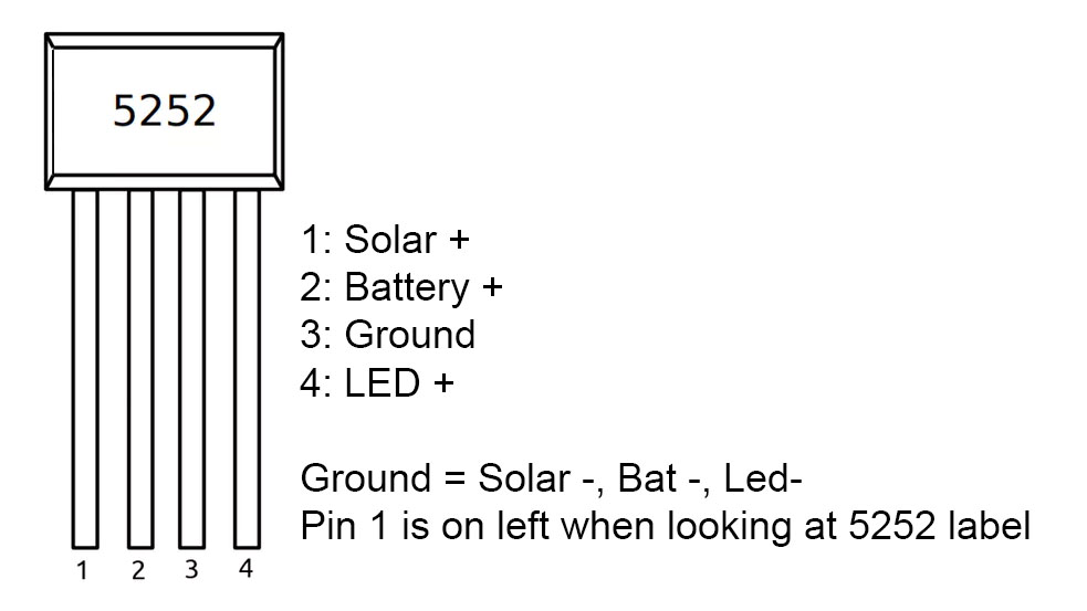
A basic solar LED will need a small circuit board piece, one 5252 part, and a 220uH inductor. You will need a rechargeable 1.5 volt battery, and a 2 volt solar panel. I used 26 gauge silicone coated wire to hook everything up, and soldered the battery directly. A switch is another place to go bad, water gets in on/off switches and ruins them, and your solar LED quits working. The 5252f part will output 3mA to 300mA, and up to 1.5 volts.
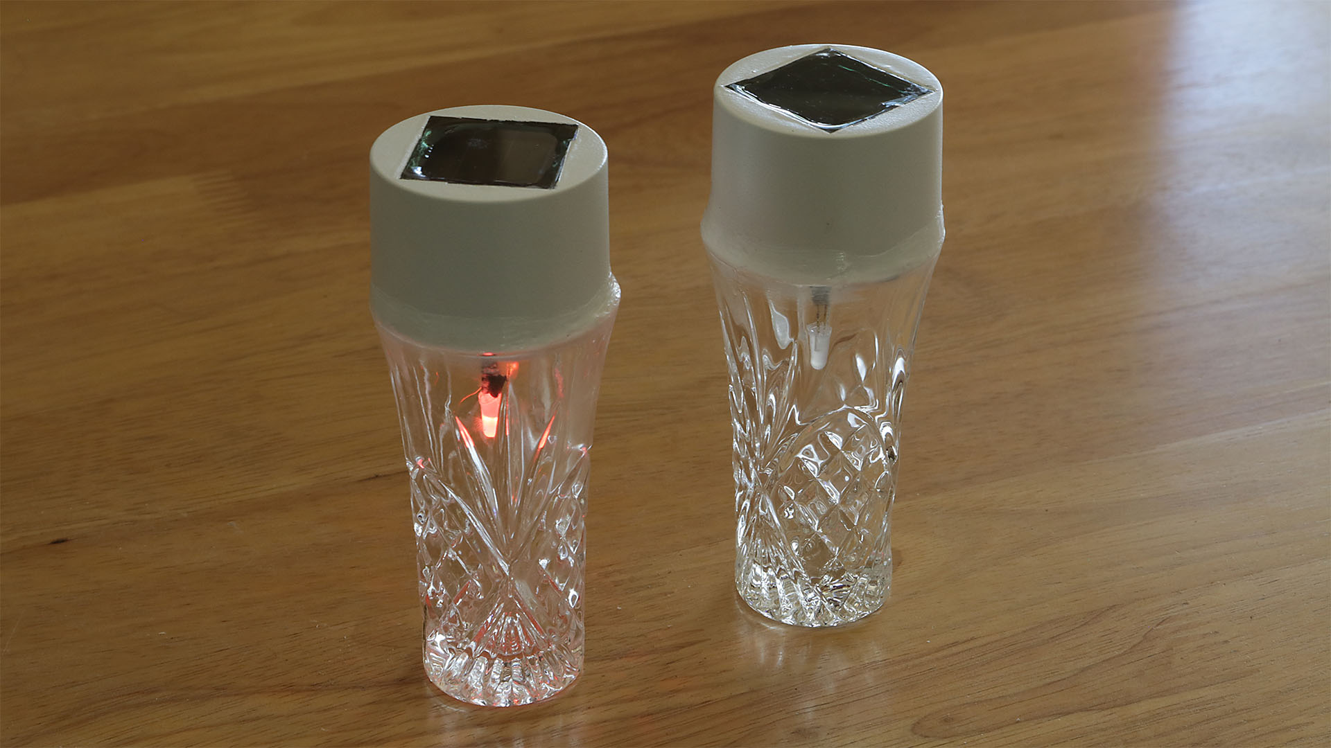
For this article, I made some color shifting LED solar lights. A color shifting LED can be purchased, and then all you need to add to the 5252 part and inductor is a capacitor and a diode. The capacitor is a .1uF or 104 capacitor (I used a 50 volt). The diode is a BAT85 200ma, 30 volt diode. I think a clear glass container works best for this project, since the LED changes colors. The color shifting LED I used is called a 5mm RGB slow flashing LED.
You will need to solder to make this project. I also have links below to a soldering iron, to help you get started if you haven’t done that before. I bought the parts in bulk. The 5252f, inductor, capacitor, diode and LED’s can easily be bought in bulk, so if you make multiples of these, those parts end up being very cheap per each solar light. You can always make a lot of these to give away to friends, family, neighbors, etc. What I found the most expensive was the glass I was putting the LED in, followed by the battery.
A 220uH inductor works well for a standard LED of about 20ma. Or you could use higher values, for example a 330uH to get a slightly lower brightness, but have the LED last longer through the night. For a very bright LED such as a .5w that takes 100ma or so, you would probably use a 33uH or 47uH inductor, again, the higher value, the less current, and longer it will last through the night.
Here’s a chart of various inductor values, so you can get an idea how many millaamps each one will output. If you are getting a brighter LED for example (that takes more power), you’d want a lower value inductor.
330uH puts out 11mA
270uH puts out 14.5mA
220uH puts out 15.5mA
150uH puts out 25mA
100uH puts out 34.5mA
82uH puts out 38mA
56uH puts out 50mA
47uH puts out 75mA
33uH puts out 110mA
The above values can be calculated for other inductor values (if I figured this out correctly), by taking 3750 divided by inductor value. This will give you the milliamps that the circuit will output. For example, 3750 divided by 100 = 37.5 (close to the 34.5mA in the above chart numbers I found online).
To figure out the inductor value for a given milliamps desired take 3750 and divide by the mA wanted. For example 35mA/3750 = 107uH, or round and get a 100uH inductor.
The cheapest way to buy the parts is probably in bulk. If you just want to make 1 of these, I don’t know where you’d find one of each part, but the price would be a lot more. So consider that you can always make several of these, and probably still have leftover parts.

You can get either AA or AAA rechargeable batteries. AA batteries will take more of a charge, thus could be used with a larger solar panel, maybe 100ma. I used a AAA battery to fit in the solar cap I bought, also purchased in bulk.
Start with making a circuit board. I bought some little pieces and cut them down so each small piece had a 4 x 6 hole pattern in it. This size works great for a color shifting LED project. You can make it smaller I’m sure for a solid single color LED, as you won’t need the diode and capacitor. I’d say for a one color LED project, a 3 x 5 pattern of holes would be large enough. When cutting the PCB board, cut down the middle of a row of holes.
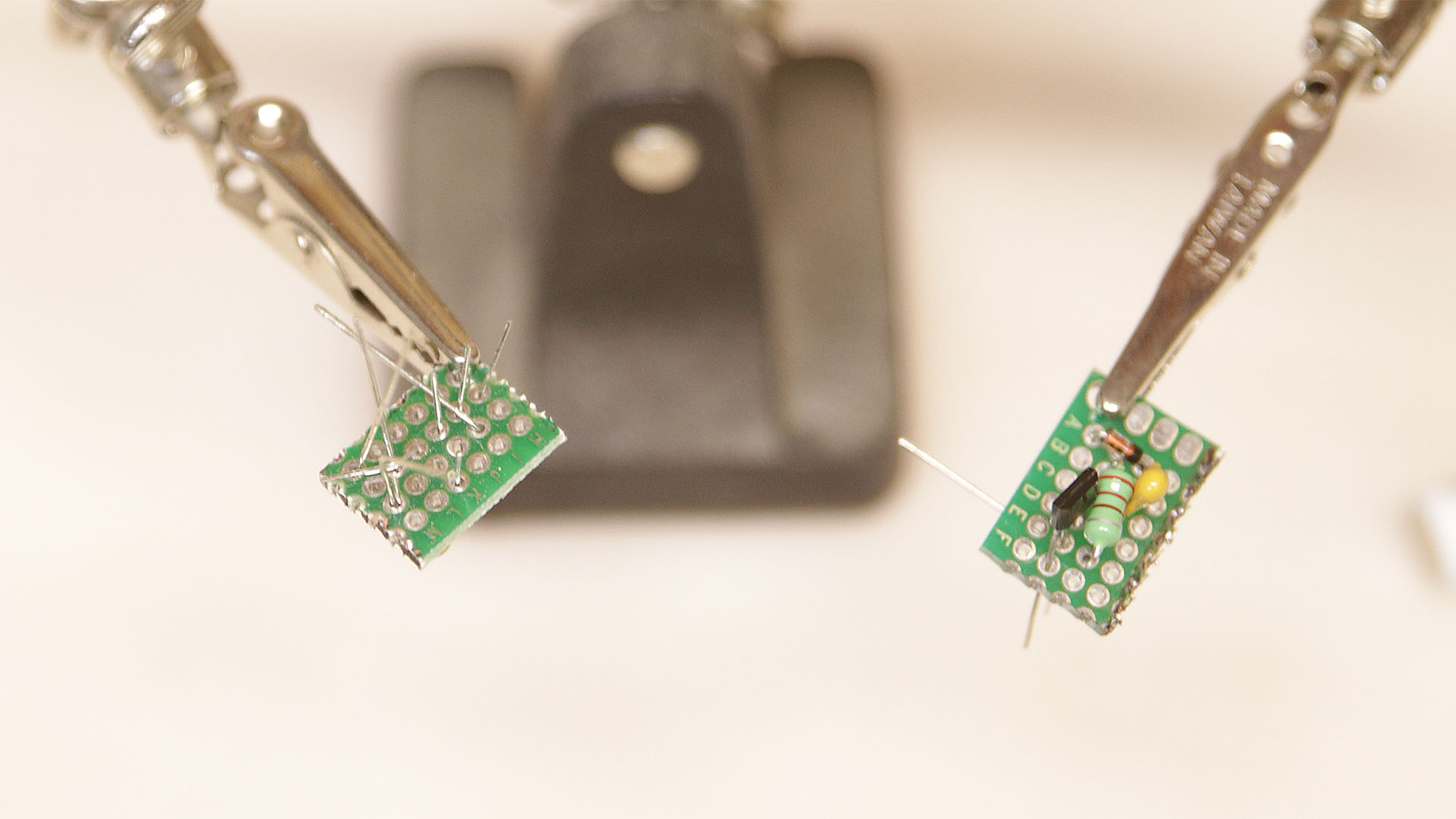
Layout the parts according to this image of the back of the circuit board. What you are looking at is not the parts side, but the side with the leads, where you will be soldering the parts together.

Connecting the circuit takes bending the leads over so they reach the next pad. For example: pin4 can be bent to the left to hit the inductor, the inductor lead can be bent to the upper left to hit the diode. Then solder at the inductor to pin4, and at the diode positive side. Clip off the excess leads.
At the bottom near the middle, bend the capacitor lead upwards and over to pin 3, the ground. Bend pin3 up and near the hole for the ground wire. Solder pin 3, and trim off any excess from the capacitor (if any). Leave the pin3 bent upwards towards where the ground wire will connect for later.
Bend the inductor upwards to pin2. Bend pin2 upwards next to the hole where the wire will be connected to the positive side of the battery. Trim any excess off from the lead from the inductor, leaving pin2 still going up towards the positive battery hole, which we’ll do later.
Pin 1 of the 5252F is bent up towards where we will solder the wire for the solar panel positive lead. When you solder that lead, make sure you also solder the wire from pin1, which should be bent so it is right there touching the wire going to the solar. The wire itself will be on the other side of the board, just the end of the wire will be barely poking through this back side of the board.
I used 26 gauge silicone covered wire. I like this wire, as if you accidentally hit the insulation with the solder iron, it will not burn off. It is very flexible wire also. I got a set of the wire, which had five different colors of wire, with about 33 feet (10 m) of wire for each color. This is great for many projects.
You will need four wires connected next. The wire itself is on the component side, so I can solder the wire on the back of the board. The length of wires will depend on how you are connecting your project together, and how far your LED and solar panel and battery will be. Mine were pretty close together, so my wires are all about 1.5 inches long (40mm).
I used a yellow wire for the positive going to the LED. Cut that and strip off the insulation on both ends. You won’t need to strip off much insulation, enough to go through the circuit board and stick out a little, and just enough to be soldered along the positive LED lead. On the bottom left side, make sure at least one of the capacitor or diode- leads is bent over and going near the corner hole you will use for the LED wire. Stick the wire through the board and solder it on, making sure the capacitor/diode wires (both come through the same hole in this case) are soldered with the yellow wire. Make sure the hole with the two wires coming through is also soldered, and cut off excess leads.
I used a black wire for the ground wire. Since other wires will be connecting to this, I used one wire coming off the board, and connected the other three wires to this wire. I cut more insulation off the end of this wire, to allow for easily connecting the other three wires. Bend pin 3 up alongside the ground hole. Put the wire with the end with only a little insulation removed through the ground hole, next to pin 3. Solder the wire in place, making sure to solder the pin 3 wire resting on it also.
I used a red wire to go to the positive side of the battery. Remove some insulation off both ends. Bend pin 2 up right alongside the hole for the battery plus wire. Push the wire through the battery plus hole from the component side, next to pin 2. Solder the wire in place, making sure to solder pin2 also.
The last wire to the board is for the positive solar. My solar cap already had a wire, so I just used it. Bend pin1 up alongside the solar positive hole. Put the solar wire in from the component side, and solder it in, making sure to solder it to pin1 at the same time.
Cut two black wires to attach to the black ground wire on the circuit board. One will go to the battery negative, one will go to the LED negative. My solar cap already had a negative wire. If you are using a basic solar panel, but a third wire for the negative of the solar panel. One each of the cut wires, strip the insulation off one end a bit more than usual, to make it easier to connect them all together for a ground wire. Twist the four ground wires together and solder them.
I slightly sand the battery ends to clean them up so solder sticks well. Attach a bit of solder to both ends of the battery. Try to make this as fast as possible, as batteries can be damaged by extreme heat. You can always put a metal wrench or screwdriver end onto the end of the battery when you are done, to try to bleed some of the heat into the metal tool, and out of the battery.
Solder the red wire to the positive side of the battery, and one of the black wires to the negative side of the battery. Solder the positive side of solar panel to the wire from pin1 if you aren’t using a solar cap (if you are using a solar cap, the wire was already there, and you should have soldered it on already).
Now put some heat shrink tubing around the wires of the LED. Alternatively, you can use some tape, or even silicone to put around the leads so they don’t short out. If you use heat shrink tubing, put some on the LED leads, but leave some lead sticking out. Put a couple short pieces of heat shrink tubing on the two wires you are going to solder to the LED. Solder the LED, the longer lead is the positive lead so hook the yellow wire to that. Solder the remaining black wire to the shorter LED lead. When you do this, your LED should light up if your battery has a charge.
Another way to tell the LED leads apart, the negative lead usually has a flattened edge on the round LED.

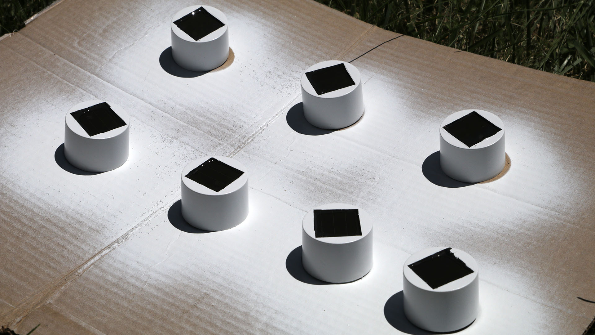
I used a toothpick to drip epoxy around the edges of the glass covering the solar panel on my solar caps. The idea was to keep the water out from under the solar panel. Water is a major issue with these solar LED’s, so you want to try your best to make sure water can’t get inside these. Maybe this was an overkill, but I feel better knowing water can’t get under my solar panel. Just a word of advice about epoxy: I had a lot of trouble using the Loctite epoxy I’d get at the local box store. This stuff was of terrible quality and comes loose. I bought a couple of larger bottles of epoxy (yes, epoxy is expensive!), but maybe you can try something like the Gorilla brand (I haven’t tried that yet, let me know how it is in the comments). One more hint: if your resin ever crystallizes, don’t toss it out! It is like honey. Stick it in the sun, and it will turn liquid again.
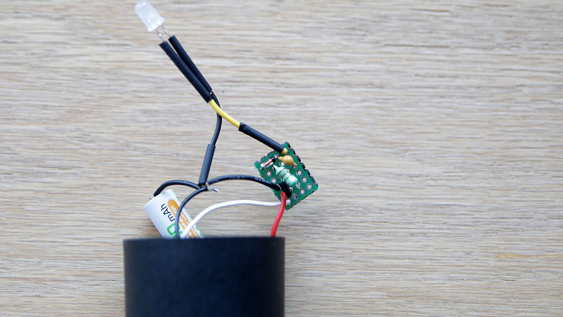
I put the battery inside the plastic cap at an angle, with the circuit board. Make sure the circuit board it set so that it doesn’t short out against the battery. I then used silicone to glue the parts in place. I used my little holder to hold the LED upright (since the entire assembly is upside down), so it will hang down inside my glass. Then I dabbed silicone on the battery and LED wires, once the silicone dries, that holds the LED in place so it will hang in the center of the glass.
I then used my finger to place three dabs of clear silicone around the edges of the shot glass. Since the shot glass and the solar caps had about the perfect diameter to be glued together, I could glue them together directly. The three dabs of silicone, once dry, hold the cap in place, so I could put a line of white silicone around the edge. The white silicone not only holds the solar cap on, but it keeps water out of the inside of the glass. After putting a thin line of white silicone around the edge, I double check to make sure there are no holes in the silicone, if so, I smooth those slight with my finger. Making sure there are no holes, makes sure no water gets in a hole. Then I spray a soapy water mix on the lid, and my finger, and make one pass around the edge of the glass, which smooths the silicone almost perfectly.
If your project doesn’t fit perfectly together, one idea I had was to cut Plexiglas pieces to fit the top of the jar or glass container. Then I can either mount the solar cap, or just a regular solar panel to the Plexiglas. If just a regular solar panel, the circuit board and battery can be mounted under the Plexiglas, inside the container. You’ll need to drill a small hole in the Plexiglas for the wires. Make sure the everything is well sealed. Water damage is the leading cause of issues with garden LED lights.
I used Godinger Dublin shot glasses, a cut crystal look, which throws the LED light around in interesting patterns. The solar caps fit the top of the shot glass very well, and just need to be siliconed on. I did have to remove a couple of the solar caps on glasses that friends had dropped (without breaking the glass!). That knocked out the circuit board from the cap, which I hadn’t attached well enough to the cap. My newer versions I tried to make sure are attached much better.
With a AAA battery, during the summer, these lights are still going in the morning when the sun comes up. I’m not sure how long they’d last in the winter with the shorter days and longer nights.

I think these LED lights will last quite a while. Water can’t get in them. There’s no switch to get wet and go bad. The wires are nice quality, and won’t easily break off. Until the battery goes bad, these should work nicely for years. Which is quite the opposite of the ones you buy.
I’d love to hear how your project went in the comments. Also please comment if I have a mistake, or you found a better way to do something. Thanks!
Tools:
budget soldering iron: https://amzn.to/2Sn89BT
Better soldering station: https://amzn.to/2G9Jviu
budget multimeter: https://amzn.to/2DRAjwU
Better multimeter: https://amzn.to/2G7CXRx
battery tester: https://amzn.to/2MOxkba
wire stripper: https://amzn.to/2t73HJa
I didn’t need a multimeter for these new solar LED’s. I lucked out, and each one I made worked the first time. It is possible you may need one to help locate issues.
Parts:
Silicone sealant (clear): https://amzn.to/2DTrmmR
Silicone 10.1oz tube, white: https://amzn.to/2DVakqy
Circuit board pieces (could make 36 circuit boards): https://amzn.to/2FdrDUH
Heat shrink tubing to insulate wires: https://amzn.to/2XSmgR5
Shot glass (set of six): https://amzn.to/30I9eaQ
QX5252F Solar LED IC driver: https://amzn.to/2Gtzyvt
LED Kit (replace or change colors): https://amzn.to/2GlWa19
LEDs, white: https://amzn.to/2t3wZs4
RGB Slow Flashing 5mm LED: https://amzn.to/3iwUiCp
Silicone covered wire: https://amzn.to/2MMmZfR
AAA NIMH battery: https://amzn.to/2GlKaN6
AA NIMH battery: https://amzn.to/2MTX6uL
0.1uF capacitor for color change option: https://amzn.to/3iqPnTx
BAT85 200ma 30 volt diode for color change option: https://amzn.to/31FGxdY
Inductors 220uH 1W: https://ebay.us/tn7Bir
Solar Panels:
Solar caps (quantity 10, other quantities available from seller): https://ebay.us/YrdRD3
60mA 2 volt round (qty 5): https://amzn.to/33HkA0G
60mA 2 volt square (qty 5): https://amzn.to/3ixlTU9
160mA 2 volt square, low light locations (qty 5): https://amzn.to/3ixmiWF
wow very nice project to do thanks for the information
Thanks for all this valuable information. I’m still learning, and this will help me a great deal to achieve my own goals to make my own custome solar garden lights.
Can you post a picture of just the simple circuit board and not the color shifting circuit board?