

I was disappointed trying to find articles or videos on how to repair the LED garden lights. In this article, I’m going to go over everything from maintaining to repairing your LED garden lights, instead of tossing them when they go bad. Depending on the value of the light, you still may want to toss the very cheap dollar or two lights, by if you have some nice ones, you can get them working again. I am veering off my normal woodworking, but I will get back to that soon. I am planning on making some color changing glass lights for the yard, as well as another project to make a light up house number that will also be solar powered, and have a nice wood frame.
I’ll start of with the easier items. First is maintaining the lights. If you have new ones, or ones still working, now is the time to start with those. The biggest problem with failures is water leakage into the electronics area. I used clear silicone sealant around the solar panel, and around the electronics box. You don’t want water getting under the solar panel or in your electronics box.
Do you have the solar panel facing south?
Make sure the solar panel faces south. I have some of these that would look better facing the wrong way, but if the solar panel faces north, it isn’t going to get a good charge on the battery. The panel needs to face to where the sun is to get a good charge. Also check that it is getting sun, and isn’t shaded from something.
Remember, many cloudy or rainy days will make it so the battery doesn’t get a full charge. The light may not come on or may only last a short while before shutting off. Solar panels charge the battery very poorly during rainy days.
Check The Switch
Is the switch turned on? You need to cover the solar panel to simulate darkness in order to test and get the LED to come on. Make sure it is in the “on” position. Also – the switch is one of the most vulnerable places to corrosion, more on this later.
It needs to be dark to come on
If there are outdoor lights, this may prevent the light from coming on. The LED doesn’t light during the day when it is charging, and only comes on when the solar panel is dark. You can test it during the day by covering the solar panel with your hand.
Is it getting wet inside the electronics?
Start by making sure your solar light is dry. You don’t want to end up sealing water that is already inside. Open up the electronics box, if you can and dry it out. Put it back together and seal around the edges with silicone.
I used a toothpick with a tiny bit of silicone on it to seal around the solar panel, without getting too much silicone on. Seal the crack up so water can’t get under it.
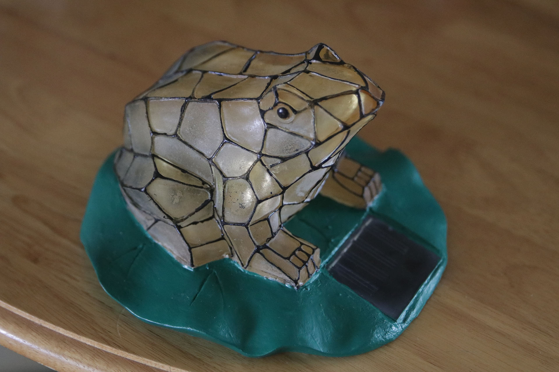
On my solar glass frog, with a plaster of paris base, I sealed that up with some paintable caulking. Again, I used a toothpick to not get too much caulking on and just seal in the tiny little cracks. I’m going to repaint the base, and I want the paint to stick to the caulking. Paint won’t stick to pure silicone caulking.
Solar panel getting hazy?
The other issue in the long run is that the solar panels with an epoxy covering get a white haze on them over the years as the sun damages the epoxy. I think putting a regular coating of car wax on them every 6 months may help, I’ll be trying that out. If it is new, use a bit of car wax on the solar panel, same directions as waxing your car. If it already has the white haze, start with car polishing compound. Really rub the solar panel, I used a small piece of paper towel to apply and polish the solar panel, followed by another clean paper towel to clean that off after it dried. Now use a different paper towel, and wax it with some car wax. The white haze should be gone, and you should be able to see the solar panel under the epoxy easily now.
Some solar panels are covered by a piece of glass. These don’t get a haze, and I only seal around those with silicone so water can’t get under them.
If your solar LED is working, wait for the silicone to dry, you are ready to put it back outside. If it is broken, read on, for the most common solutions below. I’ll start with easier ones, but you will need a soldering iron or multimeter for some of them. If you have a problem with your I didn’t cover, please comment, what was wrong with yours.
Still not working? Time to take it apart
If it is not working, you will need to figure out how to take it apart. This is a last step after you’ve tried the other steps above.
Some are not meant to be taken apart. One one of mine, the solar panel was also where the battery was, and it was glued in somewhat permanently. I used a box cutter to cut the glue around the edges and managed to get that pulled off. Some have tiny Philips screws. Some Phillips screws are hidden and protected under a tiny round rubber plug in the electronics base.
Once you open it up, take several pictures of the circuit board and wires. The wires easily break off, and usually have horrible solder connections. When multiple wires break off, it is hard to know what went where. Some circuit boards are labeled, some are not. Most of the circuit boards only have two parts, a 5252F 4 pin chip, and one inductor (that looks like a resister usually). They call this type of circuit a “joule thief”, as it powers a 3 volt LED from a 1.2 volt battery, and does so in a way that uses little power from the battery. Some circuit boards have hot glue or something on them, I always have to carefully remove that, in order to get down to see what the issue is. Of course, there’s a risk it may never work again, but it doesn’t work now – so what is there to lose? In a few months, I’ll have an article on how to build a new circuit board, so hang on to any broken ones you really want to fix.
Check the battery
Starting with the easiest first, you can check the battery. Most of these I have, have a battery clip, with a AAA or AA battery in them. They are usually NiMH batteries, so are rechargeable. Some have the battery soldered in. If yours has, pull the battery out, and put a regular battery in its place that you know is good. Cover up the solar panel, does it work now? It may be the battery, or perhaps the solar panel isn’t charging the battery.
One video show the guy cleaning his battery terminals and switch with WD40. I’m not sure how good this would work, but you could try it out. Clean off the excess oil afterwards. If the battery shows signs of any kind of leakage, replace it. You can buy NiMH batteries online, in either AA or AAA size.
If you have a battery tester or multimeter, you could check the battery, does it have a charge? If so, that means the battery and solar panel are working. A battery tester is separate from a multimeter, and is nice because it puts a slight load on the battery, helping to determine if it has a good charge or not.
Inspect the circuit board
If your circuit board has a 4 pin black chip in it that says “5252” on it, and one inductor (that looks like a resistor), I can tell you how to check it. The inductor goes between pins 2 & 4 of the chip, and raises the voltage of the battery up high enough to power a 3 volt LED. The circuit also turns the LED off and on about a hundred thousand times per second. This saves battery power by having the circuit off part of the time.
If your circuit board doesn’t use the 5252 chip, you’ll just have to do your best. Some of those boards still label S+ (solar positive), B+ (battery positive), and L+ (LED positive), so if a wire fell off, you may still be able to figure out where to reattach it. The rest of the article is mostly for the little boards with a 5252 chip and one inductor. Note there are also some solar LED’s that have a color shifting LED. These can use the same 5252 chip, but also have a couple more small parts on them. In this case, the LED solders onto the other side of a diode (which comes from pin 4 still), and the LED is in parallel with a small capacitor.

On the breadboard above, if you aren’t familiar with breadboards, each of the 5 rows in the middle is connected vertically. For example, pin 1 (on the left side) on the 5252 4 pin chip, as you go down, is connected to the positive red wire on the solar panel. Another example, pin 3 is connected to the black ground wire. Pin 4 of the 5252 is connected to the red wire going to the inductor, and also to the blue wire going to the positive side of the LED. The top two rows are connected horizontally. The blue line above the top row is the ground row, any black wires going here are connected to ground. The second row I didn’t use, but is usually a power row, for all point needing power.
Inductors are of various values, hopefully you can just use the one in your LED light. A 220uH value, is good for a 20ma LED. Or you could use higher values, for example a 330uH to get a slightly lower brightness, but have the LED last longer through the night. For a very bright LED such as a .5w that takes 100ma or so, you would probably use a 33uH or 47uH inductor, again, the higher value, the less current, and longer it will last through the night.
On LEDs, if new, the longer wire is the anode, or positive side. If already installed, the wires may have been trimmed so you don’t know which was longer. Some LEDs will have a flat side when viewed from above, this is the cathode or negative side of the LED. If you are unsure, you can hook an LED up to the circuit board and try either way, it won’t hurt the LED to be hooked up backwards. Be aware though, an LED normally needs a resistor in place when hooked directly to a power supply or battery, or it will take too much current and can burn out. When hooking up an LED to pin 4, with the proper inductor in place, you will be fine.
If you wished, you could try changing the color of the LED by buying a new pack of LEDs, and choosing a colored one instead of whatever LED was in your garden light. This option may have issues, as different color LED’s take different voltages, usually less than the white LED’s. It is possible to burn one of those out. You may need to change the inductor to a higher value. I’ll go more into picking inductors when I go over making a complete new solar LED circuit board in a few months. I get my inductors from eBay.
Do you have a multimeter?
If you have wires that have broken off, you will need to solder them back on. If you want to test further, you will need a multimeter to check voltages and continuity. If you don’t have these items already, I’ll have some links to some cheaper ones, and some medium priced ones. Note that it may not be safe to use a cheap multimeter on your 120 volt or 240 volt main power. But they will be perfectly safe testing low voltage items. One of the big reasons for higher priced multimeters is to make them safer for using on higher voltages. A cheaper multimeter may say it goes to 600 volts, but it would not be a good idea to try that out. If you do get a multimeter, keep in mind, you can use it for many things in the future. My multimeter is a fairly cheap one I got from Radio Shack decades ago. I’ll probably be upgrading my multimeter soon though.
Do you have a soldering iron?
If you don’t have a soldering iron, I’ll list a fairly cheap one that will get you going and able to solder wires back onto your solar garden light, and even comes with some solder. If you think you may have a use for soldering other things, it may be a good idea to get a slightly better solder iron. You will need to buy some solder separately with the better soldering iron I won’t go into soldering too much, as that’s a skill that takes some practice. But one thing to remember is to only heat up the area just long enough to melt the solder. Heating electrical components for a long time will ruin them. For this type of soldering, a solder gun would be too much, it would get too hot a could damage components fairly quickly. I use my solder gun for much large wires, and a solder iron for small stuff.
Checking and replacing broken wires
If a wire broke off, sometimes it gets too short, and sometimes I can’t get the insulation off without breaking more wire off. Sometimes the wire itself after removing a bit of insulation off the end is a blackish color, and the wire won’t accept solder, even if I use more flux on it. In these case, I just replace the wire. I found some great silicone covered wire that solders easily. A lot of times I just use wire cutters to strip the insulation off the ends of the wire, but this wire stripper works great also.
When checking wires and voltages on the solar LED lights, don’t trust any of the original wires. I saw one video where the solar LED wires, red was negative, and black was positive, the opposite of normal! Be sure and check everything. Test the voltage of the battery at the battery, then on the battery holder, the battery holders are cheap and go bad.
Check voltages and Continuity on the main sections of the circuit
Solar Panel – Pin1
The way I start is to put the multimeter to DC voltage, and black probe on ground (the negative of the battery is a good spot), and the put the red probe on pin 1 of the 5252 chip. See the above diagram for finding pin 1. This will read the solar panel voltage. If there is some light in the room, you should be getting at least half a volt reading, and up to about 2 volts in the sun. If there is no voltage on pin 1, there is probably a bad wire somewhere. Start by going back to where the (hopefully) red wire from the solar panel is soldered onto the board, in a place that ends up going to pin 1. If that looks good, then the problem could be the ground wire of the solar panel, check that this goes back to the ground on the circuit board.
The Switch
Then check the switch. The switch is one of the first parts to go, from corrosion. I usually cut the switch off, or if it in installed permanently, just take the wires off, and solder those together. You can use the continuity setting on the multimeter to check the switch, by putting it onto the two pins the wires are soldered onto, it should beep. If not, the switch is bad (try switching the switch first and checking again).
Battery Power – Pin 2
Do the same thing for pin 2, which is the battery. Is there power on it? If no, try replacing the battery temporarily with an alkaline battery you know is good, do you see power on pin 2 now? If not check that the positive wire from the battery comes to the circuit board. The next place the wire will go is to the battery holder. This is another place that can have a bad connection, or the wire can break off. It is usually very difficult to solder onto the end of the battery holder, that type of plated metal doesn’t take solder easily, and the wire will pull off some of the plating and disconnect again. The connections may be corroded. Try cleaning those off and seeing if that helps. Put the meter back to DC voltage, with one probe on the negative side of the battery, does the voltage get to the battery holder? Sometimes that is where the problem is. Does it get to where the wire is soldered onto the switch (if it is still in place), or the circuit board? Find out with the meter where you are losing the voltage, and fix the wire or battery connector or switch. If that is all good, do the same thing with the ground side of the battery, and follow that back to the circuit board.
Now do the same thing for the LED on pin 4. Test it while covering the solar panel, as the LED doesn’t get powered up unless it is “dark”. Oh,m and you must have successfully tested pin 2, the battery power, and have a battery with power in it for the LED test to work. Test the power at pin 4, and all the way back to the LED, and then the same with the negative wire to the LED.
LED’s have to be powered a specific way, or they don’t work. With voltages as low as these, you can just try it out one way, then the other way. For example, I used a new LED, and just put the wires directly onto pin 4 and the ground by holding them there to test that a new LED worked. Then I followed the wires to find the issue. You don’t need a new LED to test it that way, you should be able to easily do the same thing following the voltages on the circuit board and wires.
Hopefully by now, you have found the issue and fixed it. I’ve never had a bad solar panel or LED yet, And only one time was my circuit board badly damaged enough not to work. I had to replace that circuit board with a brand new one I made. More on that in a future YouTube video and article. But if the problem is the solar panel itself, or the LED or your circuit board, you can also replace those items and still get your favorite garden LED lights to work again.
I hope this article helped fix your favorite garden solar LED light. Next I just need to put a fresh coat of paint on the base of my glass frog light. I got a small bottle of outdoor acrylic paint from Michael’s that I am hoping will look good. I also just found out it wasn’t made of glass, but a resin material.
UPDATE: One day after the video and article are done, the one frog quit working. I had repainted the base, as not only did it look bad, but water was soaking into the base and getting inside the frog where the LED was. I took it apart, cutting the silicone off, and tested power at the LED with my meter with the solar panel covered. Zero volts. I opened up the electronics box and tested power at the battery: 0.9 volts, right at the level where the 5252 turns the circuit off. That was strange, as it had just been in the sun a couple hours to charge. I put the test leads onto the wires coming off the battery holder, and the voltage was 0.02 volts. That’s no good, testing again by putting one lead directly onto the negative side of the battery, and the other on the positive battery holder wire, still 0.02 volts, the problem was the battery holder on the positive side. I took the battery out and looked it over, and the plating had come off the cheap metal piece. Another issue that can happen is the wire soldered onto that can also pull the plating off – at that point it is almost impossible to solder back on. I pulled that metal piece off, unsoldered the wire from it, and soldered it to the positive battery side. I usually use some 400 grit sandpaper to clean off the battery when soldering, that helps the solder to stick on easier. Be careful not to heat the battery up too much. For now I left the spring on the negative side of the battery holder in place with the spring, it is working for now. If that fails, I’ll remove the spring, and just solder the negative side of the battery also.
Tools:
budget soldering iron: https://amzn.to/2Sn89BT
Better soldering station: https://amzn.to/2G9Jviu
budget multimeter: https://amzn.to/2DRAjwU
Better multimeter: https://amzn.to/2G7CXRx
battery tester: https://amzn.to/2MOxkba
wire stripper: https://amzn.to/2t73HJa
Maintenance items suggestions:
Silicone sealant: https://amzn.to/2DTrmmR
Polishing compound: https://amzn.to/2DaZ8SD
Use any car wax you have or
Wax for epoxy solar panels: https://amzn.to/2t5bdUR
Parts suggestions (if needed):
Silicone covered wire: https://amzn.to/2MMmZfR
AAA NIMH battery: https://amzn.to/2GlKaN6
AA NIMH battery: https://amzn.to/2MTX6uL
LED Kit (replace or change colors): https://amzn.to/2GlWa19
LEDs, white: https://amzn.to/2t3wZs4
QX5252F Solar LED IC driver: https://amzn.to/2Gtzyvt
Hey Steve
Thank you for a perfect description of repairing solar garden lamps – now I can fix them much better than before, because I understand the basics behind them.
Sincerely
Ib Tromholt, Denmark, Bornholm
Thanks for that great article, I’m pretty handy with most things but electronics are not my field. However I now have a good idea about how my faulty garden lamp is supposed to work because the circuit seems to be exactly like what you describe.
It has a 4 pin transistor (although I cant see a number on it), a small brown capacitor(?), a diode, and an inductor, as well as the solar panel, led and battery.
I think the problem was originally caused by moisture in the switch but I was not able to repair that as it was completely corroded. I removed it and bridged the appropriate connections on the circuit board so it was permanently ‘ON’ but when I connected the battery the led just flashed once then remained off.
It was at that point that I bought this from Ebay
https://www.ebay.co.uk/itm/1-2V-Solar-String-Light-Lamp-Board-Control-Sensor-Controller-Switch-Module/254537184999?ssPageName=STRK%3AMEBIDX%3AIT&_trksid=p2057872.m2749.l2649
Having connected my battery, solar panel and led it works and light up OK but I still have two problems.
1. I dont think the light is being controlled by the solar panel because when I operate the switch the led just lights up whether the solar panel is exposed to light or not.
2. The circuit has several flashing modes which are controlled by a second switch and which I definitely dont want, I just want steady ‘ON’ when the lamp is operating.
Can you help me with this? My wife is very fond of her garden lights and I just wanted to make this work again for her, especially as she is seriously ill at the moment. Kind regards.
I looked up that controller board you bought on many sites, and don’t see any extra instructions, other than how to hook it up. I’d suspect any solar LED controller board should only have the LED come on at night. I do not know if that board has that feature or not, just that I suspect it should. If so, possibly you have the solar panel hooked up backwards? Do you know for sure you have the positive solar lead going to “S+”? Do you have a meter to test that out, so you can check? I did see that position 8 on the switch is supposed to be “all bright” which I suspect means it should just be on solid like what you are looking for. Check the solar panel polarity if you can, if it is backwards, it would explain the LED always coming on, even if the panel was in the sun. Make sure both wires from the solar panel are hooked up to S- and S+. Good luck!
Hi, I have some Lumiz solar lampions. The circuit is exactly as you described with 5252 and inductor. The battery is charging to the full capacity in sun. But it is draining very fast. There is no diode excepting the LED. I could not find any short circuit between the positive and negative of the circuit. Can you suggest me how I should resolve this problem of battery draining fast?
THANK YOU!!! The wires came loose from the switch and I had no idea how to fix it. Your comment about taking the switch out and connecting the wires to each other was just what I needed to do. The light works again!!