This was a fun project, brought up when the cartridge filter in my dust collection system finally got so clogged, that my tools, and my thien separator were all getting clogged, before I realized the problem was the cartridge filter was clogged and needed to be cleaned. I investigated different ways to monitor this, and saw people were making their own manometers, essentially a U shaped tube with liquid in it, where you can measure the displacement in inches of water, by running one end of the hose to the cartridge filter. I wondered about the water evaporating, or getting all gunky, and didn’t like that, then came across an article about a pressure sensor and an Arduino.
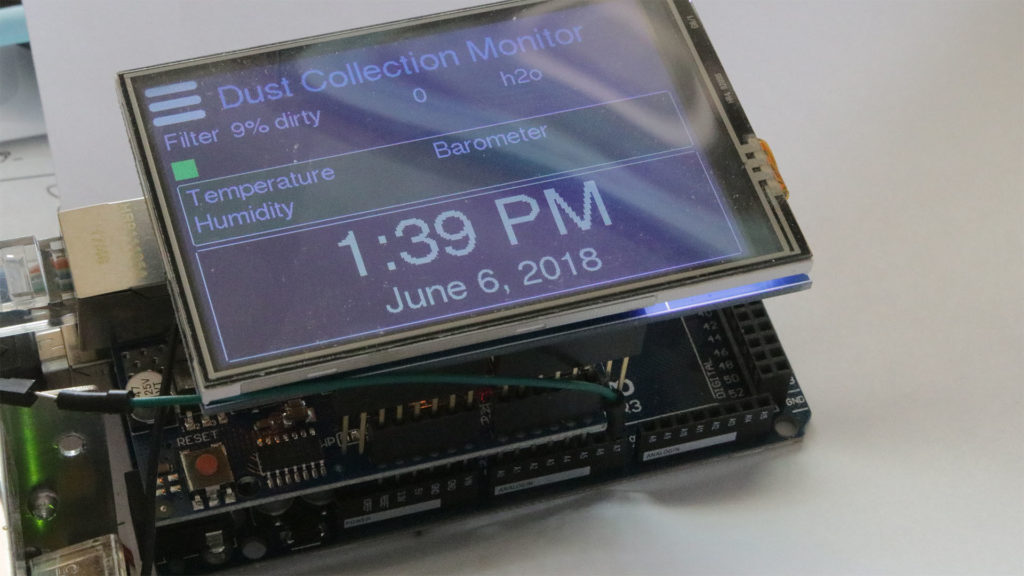
It is working fine for me, but as with all software, there are probably bugs. At this point, there are over 4000 lines of code, not including the libraries. Please comment if you find an issue. I’ve just updated to version 1.002 after a couple people had issues, I fixed several bugs, and the last few people have got it working.
I’m a programmer, so I liked the idea of an Arduino, and all electronics rather than a water filled tube. It would be a lot of fun to learn about Arduino’s and be able to program on a new project. I looked at pressure sensors, and started learning about Arduino’s. They have shields, which are little boards that plug onto the top of an Arduino, they also make even smaller boards that hook up to Arduino’s, many of these work over two wires called I2C, with an additional power and ground wire, need only 4 wires. Multiple I2C devices can hook up to the same two I2C wires. I won’t go into a lot of basic Arduino facts here, but I will in my more detailed article with the schematic and software for this project. The two I2C wires are labeled SDA and SCL.
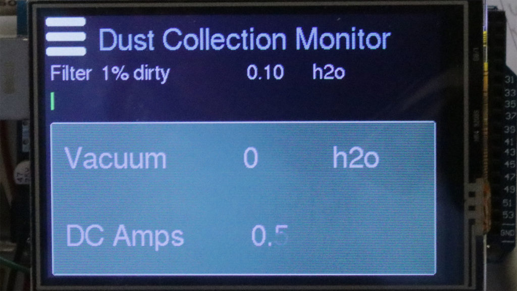
The basic idea here is this: when your cartridge filter is clean, it’s going to hold very little pressure inside it, as the air will go out easily. As the filter gets clogged with sawdust, the pressure will build because it is harder for the air to escape the filter. I decided to throw in a sensor on the vacuum side too. A vacuum sensor might show me exactly how improvements are making the vacuum better. For example, what would happen when I replace one of my hard 90 degree fittings with a better sweep 90 degree fitting? Will my vacuum go up? If so, I’ll be able to measure it and know for sure. I am not measuring actual flow going through the pipe, just the vacuum pressure. I think air flow would be a better thing to measure, so am not sure just how much vacuum I’m pulling will help.
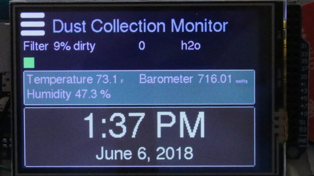
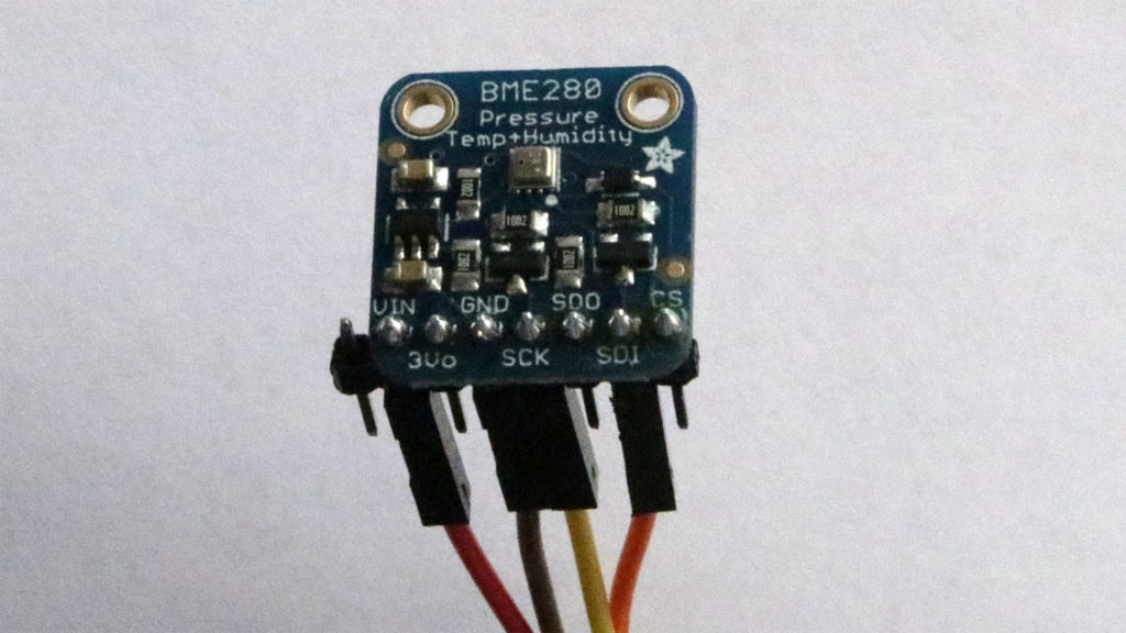
Since a lot of the Arduino parts are very cheap, I thought it would be fun to add a module that adds a temperate sensor, humidity, and barometric pressure. The BME280 module does all this. I also thought I might as well add a clock, these items would give the Arduino something to display while the dust collection is turned off. I’m using the Arduino Mega 2560, as it has more memory in it and more inputs and outputs. These are fairly cheap for a knock off brand, if you wish to purchase a genuine Arduino, which supports the company that made software, libraries and IDE to program these, I’ll have links at the bottom for both types. I’ll have a little more information about setting up an IDE to program your Arduino in my detailed article, but there is of course a ton of information on the Internet. The IDE needed to compile the source code and load it onto your Arduino is provided free, what’s why people like to support Arduino by buying genuine Arduino board rather than the slightly cheaper ones.
You do not need to be a programmer to do this. I’ve done all the programming. You will just need to setup the IDE, load the libraries needed (they are all in my download file), then set the variables at the top of the software file, which states what hardware you are using, so the software will work correctly, and only load the pieces needed. I have a lot of documentation in the software, and you should should only be needing to make changes in the very top, like this:
//Are you adding a BMP280, pressure, and temp sensor?
//This isn't necessary, but is interesting,
//change to a 1 if you have it, 0 if you don't
#define INCLUDE_BMP280 0
You will need to know how to solder. There’s no getting around that. I’ve been using a breadboard some, with the jumper wires to temporarily wire parts up with no solder, and those are prone to issues. The slight amount of looseness causes issues. It’s better to solder wires. The shields and smaller boards also sometimes need headers soldered on. I’m already on the fence with those, as I think I’m having issues with the jumper wires sliding onto the temperature sensor, which fails when it gets jiggled. So I may be soldering more of the wires. I don’t have a laptop to bring in the shop, so I’m hoping to still have some of the jumper wires that I can disconnect, so I can pull the Arduino and bring it into my office for software updates.
I’m making a small circuit board which will contain multiple places to add I2C boards, and some of the resistors needed for the amperage sensor, etc. The small board has a few wires going to the Arduino, but a lot of wires end up attaching to it, to hook up sensors and the I2C modules.
I was adding more and more options to the project, and was going to add an option of a two line LCD character display, but the little touch screen TFT display was so much nicer, and allowed me to get feedback by making “buttons” on the screen the user can press. Only having one display will make the code so much simpler. And for less than $20, it was cheap enough for me.
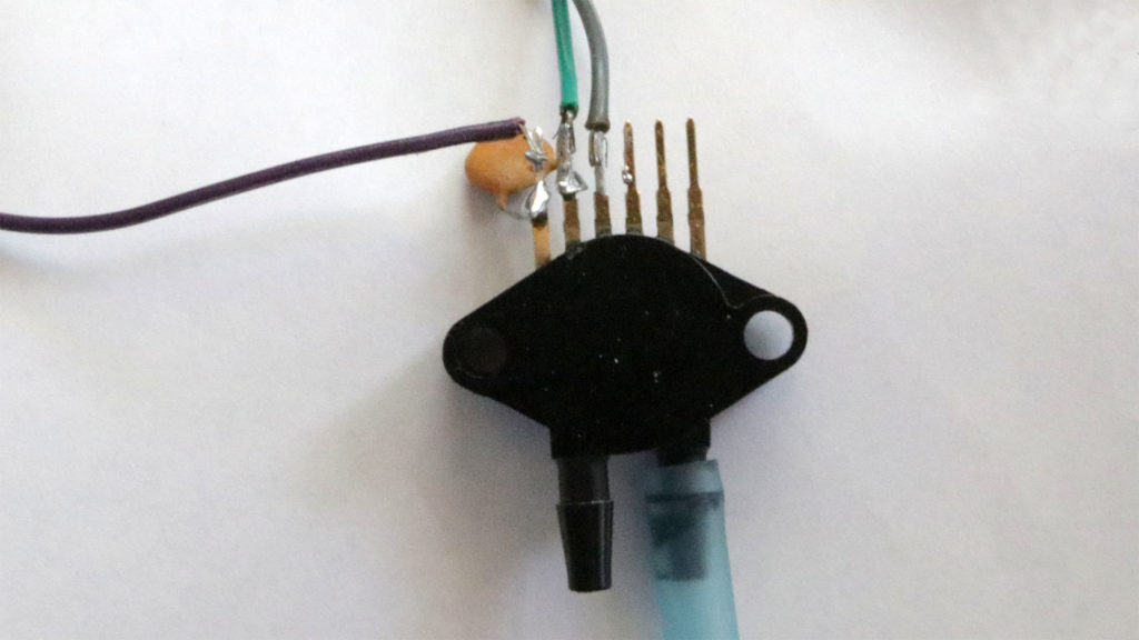
I found two pressure sensors that would work, the MPX5010, and the MPX5050. The 5010 goes from 0 to 10 kPa, and the 5050 goes to 50 kPa. 10 kPa is equal to 1.45 psi, and is more than enough to measure cartridge filter pressure. Since I am also putting a second sensor to measure vacuum pressure, and these run higher, you may want to use the MPX5050 here. That works to 7.25 psi. In all likelyhood, the MPX5010 would probably work for both pressure sensors, I’m just not sure how much of a vacuum a larger dust collection system might pull. And speaking of psi and kPa, the software allows you to configure to different units of measure, different date formats, 12 or 24 hour clock, etc. I’ll have a parts list at the bottom of the article. The pressure sensor parts weren’t available from Amazon at a reasonable price, I got them from eBay. I bought mine with no issues from the users I show below in the parts list (although feel free to purchase them through any eBay link – I don’t have any deal or incentive with these eBay users). Unfortunately, ordering them through eBay from China does take a while longer to receive.
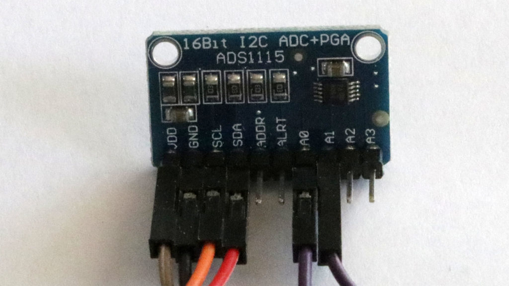
Because the cartridge pressure can be so low when the DC is on, I also decided to use a 16 bit analog input board, the ADS1115. This will give much finer resolution on the pressure sensor. You can also use the 12 bit version of this board, an ADS1015, which will also read in up to 4 analog values. The ADS1115 is much slower, but is still great for the pressure sensor. You don’t need both boards, just one or the other. The amperage sensor needs to be fast, so use an internal analog for it. The amperage sensor works by reading the value many times over more than one sine wave of the AC, to get an average amperage reading.
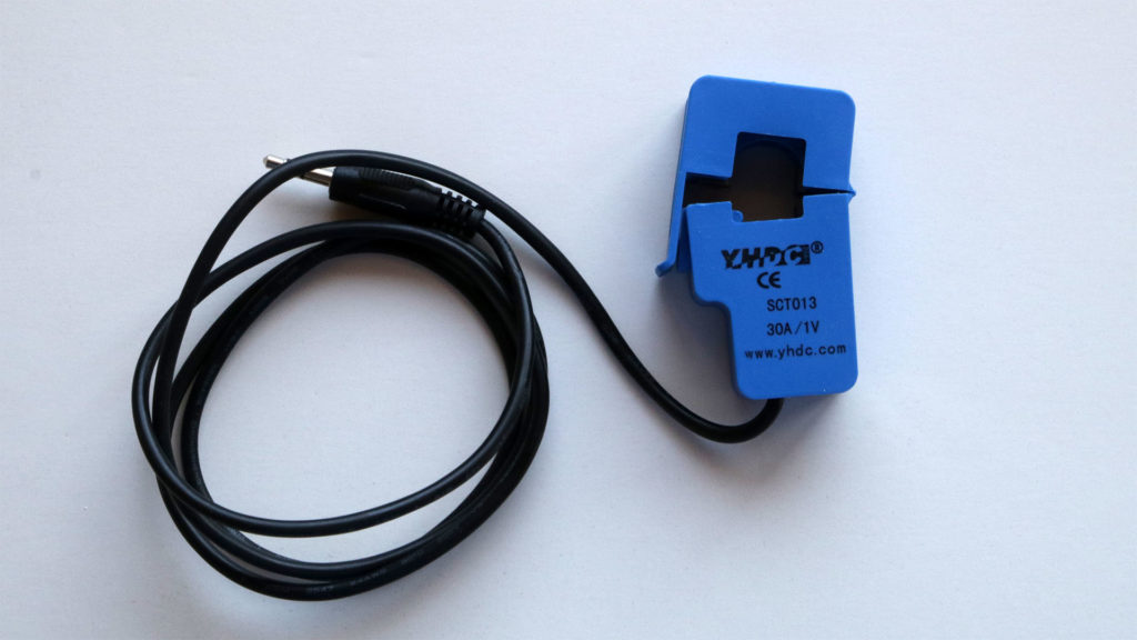
The 4 port Analog input module, the ADS1115, returns 16 bit values.After running some tests, I found the pressure in my cartridge filter is apparently only 0.003 psi when the DC is on. I just recently cleaned my filter, and that pressure is very low. I was hoping to determine if the DC was on or off based on this pressure reading, but it is so low, I was having issues with that. I decided to add an amperage sensor also, which will enable me to determine for sure if the DC is on or off. I got my amperage sensor from eBay.
I want to display how much percentage dirty the cartridge filter is, before it should be cleaned. I didn’t really know what pressure that might be. I found an actual gauge which measures this exact thing for a cartridge filter, and it says 0 to 3″ of water are OK, and between 3 and 5″ your filter needs cleaning. This gave me some important clues. It also says that SMART boost technology (maybe only on Oneida dust collectors?) has variable static pressure, and a filter efficiency gauge isn’t recommended for those systems. If your dust collection system changes motor speed based on vacuum measured, the cartridge filter pressure might tell you less, however, it still seems like it might tell you when you need to clean the filter. That will be up to you to determine.
If your dust collector uses bags, I’m not sure how that would work. You need to install the pressure sensor so that it measures pressure inside the cartridge (or maybe a bag would work too?). I used a brass barb in the metal top of my cartridge filter, and a length of silicone hose to connect to the pressure sensor.
I will always display a filter dirty percentage, even if the dust collection system is off, the Arduino can keep track of the last read cartridge pressure value, and display that. I’ll also show a bar chart of the dirty percentage. If the bar chart is green, all is good. When the bar chart changes to yellow, the filter is in the 3 to 5″ of water range, where it is time to clean it. Above 5″ of water, the bar chart turns red to let you know you are past due for cleaning the filter.
I found out some issues with the RTC clock boards. The DS3231 module I am using is great. I bought a second one for another project and this one is terrible. Come to find out, the DS3231 chips come in two flavors, and they are wildly different. If the chip says DS3231M, then it’s a very non accurate one, and mine is around 4 minutes off per day. I’ve tried in vain to buy a second DS3231SN, the more accurate version. The will have a picture os the SN chip, and send you an M chip. I contacted several eBay vendors asking them for sure which version they had. None replied, I’ll take this to mean they are selling the horrible M version.
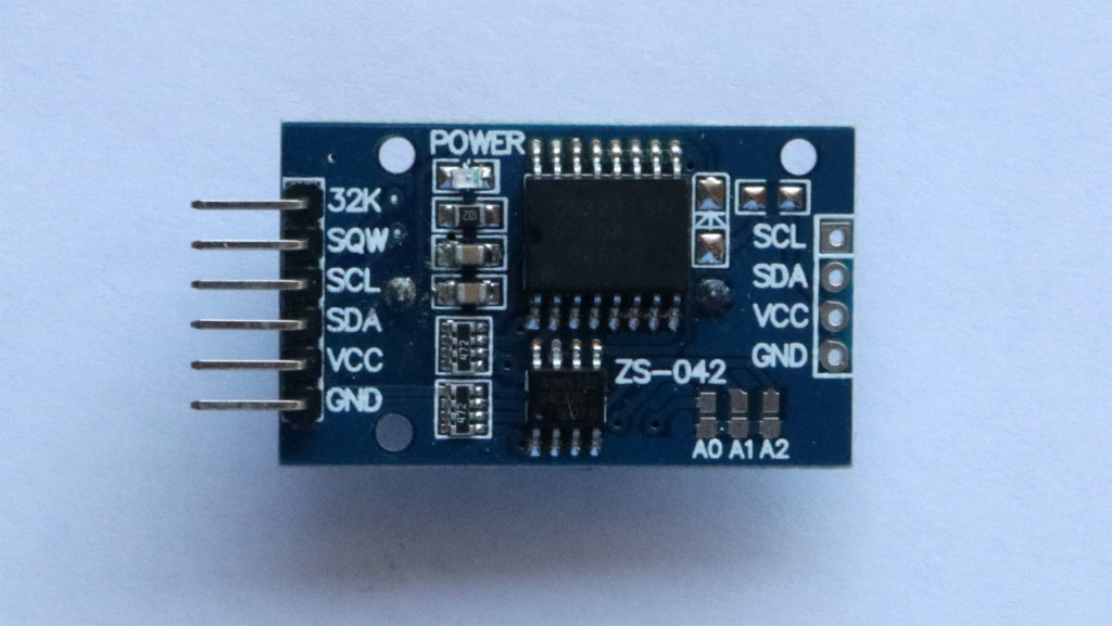
So how to keep time accurately if I can’t reliably buy a clock module? There’s a couple different ways. One is to add an Ethernet shield, and then contact an NTP server, I can resync the clock at a specific interval, and use the TimeLib library which keeps track of time using the Arduino millisecond timer, and go without the RTC module at all. I support both of these options. A third option that I don’t support (I may add it, not sure yet), is adding a GPS module. Besides telling you where you are, these tell you the exact time. And unlike an NTP server which doesn’t like you hitting the server too much, I can read the GPS as often as I want. I can use the GPS in conjunction with the TimeLib library to keep super accurate time that never needs to be reset. If you just use the RTC module, there is a set clock screen. If you have the Ethernet board to be able to use the NTP server, you will not need to set the clock, it will set automatically, and stay very accurate.
I also added a timezone and daylight savings time features, that enable the clock to reset itself for DST. I’ve got the time zones set for the main US time zones, and a custom timezone setup you can easily setup your timezone and daylight savings times if you are outside of the US mainland. Having the clock be super accurate and never need setting, as well as automatically adjusting for daylight savings time is awesome I think.
I did add in some error code to the project. Sadly, most of the libraries and other code examples have pretty much no error checking. Arduino’s are tiny, and they aren’t putting a lot of memory in them, so there’s not a lot of room for error checking, but really, I think it is a bit of a must. I’m hoping my error checking will help you if you have issues. I set up the LCD screen first, so if there’s an error setting up the other hardware, I can display the error on the screen. For example, each time an I2C device is setup, it doesn’t even check to see if a device is there (with one exception), and it doesn’t even have the possibility to return an error code. Before I open up each device, I do a check on that I2C address, and at least check to see if a device at that address responds. That really helps if you have an issue. I noticed on some of the review comments on Amazon, that people would say their device had a different default address. You can load an I2C address device finder sketch (they call each program a sketch), and determine the addresses of all devices you have attached. I added this option in the menu, so you can press it and see if the I2C addresses match what you expect to see.
While I was looking at all the Arduino pieces, I found a great video on a guy who made his Arduino turn off and on his dust collection automatically, based on if it saw any tool was on. It does this by using an amperage sensor, that the Arduino can read from each tool. He was using sensors that work by cutting the hot wire and attaching each end to the sensor board. I didn’t like this idea of running a large current tool into a tiny Chinese made board of unknown quality. I found some sensors that just clamp around the hot wire, no wire cutting needed, that do the same thing. He had servos opening and closing the dust gates, based on which tool was being used. Besides being very cool, this would be super useful. I can’t tell you how many times I’ve adjusted the gates properly, went and used the table saw, then realized I didn’t turn on the DC. Or I left a seldom used gate open too. Or I remembered to turn on the DC, but forgot to adjust the gates correctly.
Your settings will be saved in eeprom, when you update the software, you will need to still update the top hardware section, but settings such as units of measure, 12 or 24 clock, and I2C addresses of the small boards will be saved for you.
I have a screen to display run times in hours for the entire DC system, for that particular filter, and for that filter since you last cleaned it. You can reset these run times, so when you clean or purchase a new filter, you can zero that reading. For a new filter, or cleaning the filter, it also saves the date.
Remember to take care when dealing with higher voltages. My amperage sensor doesn’t need to be directly wired to a high voltage. But you will need to open up your dust collector to get to the power wires and snap the sensor around the hot wire only. Be careful doing this, unplug the tool first. I’m only telling you here what I did, I cannot recommend you do this, that is up to you to decide, and the risks are your own.
There are a lot more details in my further article with the software and schematic. This isn’t too difficult if you are good at learning new things. I’d never used an Arduino before, however I am a programmer, so that part was easy for me. And I’ve also dabbled in making little hardware projects and soldering quite a bit, although I am not anywhere close to a hardware engineer. You can start off by getting an Arduino Mega kit, that has the Arduino, breadboard, some jumper wires, and all kinds of sensors and projects and code to get you started. You start with one Sketch that does nothing but flash the internal LED on the board. Change the rate at which it flashes, and you are off to a good start in learning the Arduino.
In the parts list below, please note that some of the parts are one or the other, for example the power supply, I’m listing a smaller one and a larger one that supports the planned expansion of this project hopefully in the future. You only need one of these. Same with the Arduino, there’s a clone, the original, and the starter kit which also contains an Arduino, you only need one.
View the Detailed Article Here.
If you are making one of these, it will help support more projects like this if you use my Amazon affiliate links below to order the parts:
Arduino Mega: https://amzn.to/2HpwopC
Genuine Arduino Mega: https://amzn.to/2JAdGQY
Arduino Mega starter kit with all kinds of samples to try: https://amzn.to/2xMpzin
TFT Touch Display: https://amzn.to/2kWKSnP
Amperage sensor: https://amzn.to/2Lv07jp
5 volt 10 amp power supply (supports next project with servos): https://amzn.to/2xOBBYf
5 volt power supply (if you don’t want to do the next project): https://amzn.to/2JAP8rh
Jumper wires: https://amzn.to/2xOsNSn
Solder Station: https://amzn.to/2xUSEIb
Solder 60/40: https://amzn.to/2kUICO2
Solder (lead free): https://amzn.to/2HBbtjy
MPX5010DP sensor: eBay from user jiudi33-3
MPX5050 sensor: eBay from user specspecialty
ADS1115 16 bit analog input: https://amzn.to/2lERoA2
ADS1015 12 bit analog (you can use the 1115 or the 1015, don’t need both) https://amzn.to/2IxthMW
Optional Pieces:
BMP280 Temperature, Barometric pressure: https://amzn.to/2JnsVtt
or BME280 Temperature, humidity, barometric pressure: https://amzn.to/2JeJ5ZX
RTC Clock: No reliable sources known
Ethernet Board: https://amzn.to/2M49CqN
Header pins (needed with Ethernet shield) https://amzn.to/2LYPiHn
Bread Board (comes with the starter kit above if you get that): https://amzn.to/2HubKEU
Kill A Watt Meter: https://amzn.to/2sJfygN
Wire strippers: https://amzn.to/2Jtj3y5
Solder Flux: https://amzn.to/2Jqsy5p
Shrink tubing: https://amzn.to/2LA1hKw

